¶ 🎯 Taptic Mod Installation Guide
Add haptic feedback to your iPod Classic with crisp vibrations when scrolling and navigating. Choose the installation method that matches your skill level and preferences.
¶ 🔧 iPod Classic Taptic Mod Installation (Fully Presoldered - No Soldering Required)
Difficulty: Easy-Moderate | Time: 20–30 min | Compatible: iPod Classic 5th–7th Gen
¶ 📦 What’s Included in Your Kit
Your fully presoldered taptic mod kit includes:
- ✅ Taptic Engine (pre-wired and ready to install)
- ✅ Mounting screws (as needed)
- ✅ Double-sided mounting tape (for secure placement)
- ✅ Pre-soldered headphone jack assembly (ready to drop in)
🎉 No Soldering Required! This kit is designed for users who want the taptic experience without any soldering work.
¶ 🧰 Tools You’ll Need
Required Tools:
- iPod opening tools - For safely opening your iPod case
- #00 Phillips screwdriver - For headphone jack screws
- Plastic spudgers (Guitar Picks) - Good for opening iPods without scratching
- Precision tweezers - Helpful for handling small components
Recommended (Optional):
- Isopropyl alcohol - 99% For cleaning adhesive residue
- Anti-static wrist strap - For component protection
- Good lighting and magnification
¶ 📋 Installation Steps
Step 1: Preparation and iPod Opening
-
Power off your iPod completely
- Hold the Play/Pause button until it shuts down
- Enable the Hold switch to prevent accidental activation
-
Open your iPod
- Use your iPod opening tools to carefully separate the front and back cases
- Work slowly around the perimeter to avoid damaging the clips
Step 2: Disconnecting Components
3. Disconnect the battery
- Carefully unplug the battery connector from the logic board
- Set the front panel aside safely
- Remove the stock battery (if present)
- If you still have the original battery, carefully remove it
- ⚠️ Important: Be very careful not to damage the headphone jack/hold switch assembly
Step 3: Headphone Jack Replacement
5. Remove the existing headphone jack/hold switch assembly
- Unscrew the headphone jack/hold switch assembly from the back of the iPod
- Carefully lift it out, noting the cable routing
- Install your presoldered assembly
- Simply drop in your new presoldered headphone jack assembly
- The taptic engine is already connected - no wiring needed!
- Secure with the original screws
Step 4: Taptic Engine Mounting
7. Position the taptic engine
- Place the taptic engine where the original battery was located
- It’s designed to be the exact same size as the original battery
- Secure the taptic engine
- Use the included double-sided mounting tape to adhere it to the shell
- Press firmly to ensure good contact
Step 5: Testing and Final Assembly
9. Initial testing
- Reconnect the headphone jack/hold switch cable to the iPod
- Plug in the battery and power on the iPod
- Test the haptic feedback: Scroll through menus to feel the vibrations
- Final assembly
- Ensure all internal components are in their proper positions
- Carefully align the front and back shells
- Press around the perimeter until you hear clicks
¶ ⚡ iPod Classic Taptic Mod Installation (Engine Only - Soldering Required)
Difficulty: Moderate-Advanced | Time: 45–60 min | Compatible: iPod Classic 5th–7th Gen
¶ 📦 What’s Included in Your Kit
Your taptic engine kit includes:
- ✅ Taptic Engine with pre-attached wires
- ✅ Heat shrink tubing (already applied for wire protection)
- ✅ Extra wire length (coiled under heat shrink for safety)
⚠️ Soldering Required! This kit requires you to solder the engine wires to your existing headphone jack. Some soldering experience recommended.
¶ 🧰 Tools You’ll Need
Required Tools:
- Soldering iron - The Pincecil is reasonably priced and performs excellently
- Solder wire - 60/40 or 63/37 rosin core, 0.6-0.8mm diameter
- Flux - Rosin flux for better joints
- iPod opening tools - For safely opening your iPod
- #00 Phillips screwdriver - For headphone jack screws
- Wire strippers/cutters - For trimming wires
- Precision tweezers - For handling small components
- Desoldering braid - For removing the piezo speaker
Recommended (Optional):
- Magnifying glass or microscope - For detailed soldering work
- Anti-static wrist strap - For component protection
- Isopropyl alcohol - For cleaning and adhesive removal
¶ 📋 Installation Steps
Step 1-4: Initial Preparation
(Same as presoldered kit: power off, open iPod, disconnect battery, remove stock battery)
Step 5: Headphone Jack Preparation
5. Remove the headphone jack/hold switch assembly
- Unscrew and carefully lift out the assembly
- Set it on your work surface
- Heat up your soldering iron
- Set temperature to 300-350°C (575-660°F)
- Allow it to fully heat up before proceeding
Step 6: Piezo Speaker Removal (Critical Step)
7. Locate and remove the piezo speaker
- Find the small piezo speaker attached below the headphone jack
- Method: Gently bend the headphone jack away from the speaker
- Touch the soldering iron tip to the joint on the bent side
- When solder melts, that side pops off the flex cable
- ⚠️ Warning: Don’t overheat - excessive heat will damage audio components
Step 7: Taptic Engine Wire Preparation
8. Prepare the taptic engine
- Remove from packaging and straighten the lead wires
- Extra wire is coiled under heat shrink for protection
- Trim and tin the wires
- Leave approximately 6 inches of wire length
- Strip 2-3mm of insulation from each wire end
- Apply a small amount of solder to each wire tip (tinning)
Step 8: Soldering the Engine (Critical Step)
10. Shape and connect the first wire
- Bend each tinned wire into a small hook shape
- Hook first wire onto the top right corner from the back of flex cable
- Apply flux and solder this wire to the flex cable
-
Connect the second wire
- Hook second wire on bottom middle area from the back
- Solder to the bottom right solder point
- Note: One solder point will remain unused - this is normal
-
Test before closing
- Connect all cables and power on
- Test haptic feedback: Feel vibrations when scrolling
- Test audio: Verify both headphone channels work
¶ iPod Mini Taptic Mod Installation
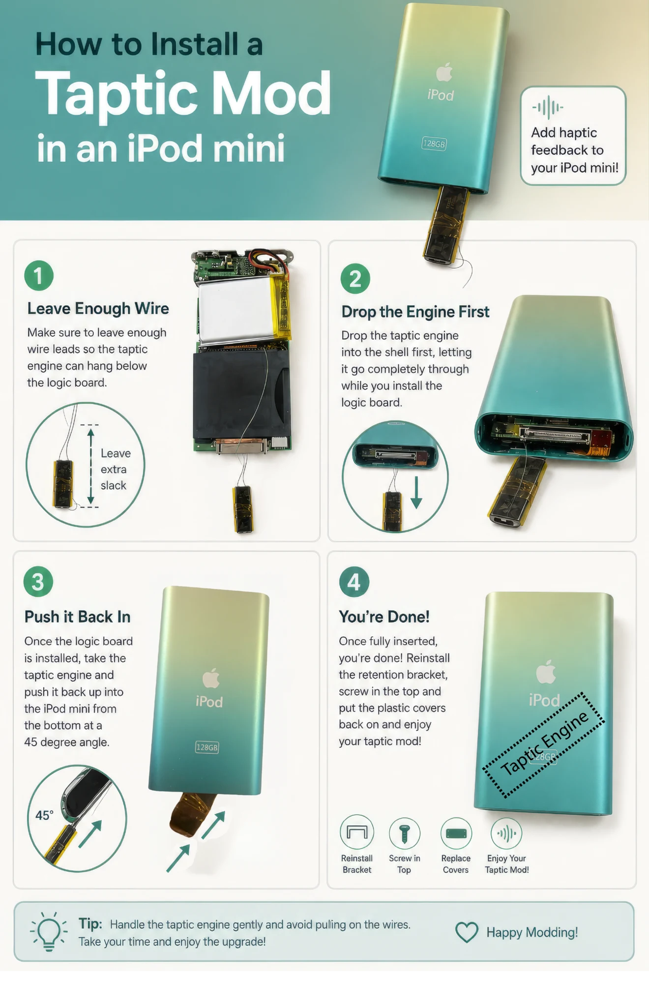
These steps cover fitting the wired Taptic engine and logic board inside the iPod Mini shell.
Handle the Taptic engine gently. Do not pull on the wires. Leave enough slack for the engine to pass through the bottom of the shell while the logic board is installed.
¶ Installation Steps
-
Leave enough wire
- Leave enough wire length for the Taptic engine to hang below the logic board.
- Keep the wires loose. Do not pull them tight against the board.
-
Drop the engine through the shell first
- Feed the Taptic engine into the Mini shell before the logic board.
- Let the engine pass completely through the bottom opening so it hangs below the shell.
- Install the logic board while the engine remains outside the bottom of the shell.
-
Push the engine back into the Mini
- Once the logic board is fully installed, hold the Taptic engine at about a 45-degree angle.
- Carefully push it back up through the bottom opening and into the Mini.
- Guide the wires as the engine moves into place. Do not tug, pinch, or sharply bend them.
-
Test the Taptic engine before final assembly
- Before reinstalling the retention bracket or top screw, power on the iPod and test the Taptic engine.
- Use the click wheel and navigate through the menus to confirm that the haptic feedback works.
- If there is no feedback, open Settings and make sure the click speaker is enabled. It may still be disabled if you turned it off before installing the mod.
- Do not finish closing the Mini until the Taptic engine is working correctly.
-
Finish the assembly
- Confirm that the engine is fully inside the shell and the wires have not been pinched.
- Reinstall the retention bracket.
- Reinstall the top screw.
- Replace the top and bottom plastic covers.
Take your time during the final fit. If the engine does not slide into place cleanly, pull it back slightly, check the wire routing, and try again without forcing it.
¶ 📞 Support and Installation Service
- Having trouble? If you think you may have bit off more than you can chew, you can mail me your iPod and I will complete the installation for you
- This service is available for customers who purchased the mod from me or from EOE
- Faulty parts? If your engine seems to have arrived faulty or stops working, reach out and I’ll send a replacement
- Contact me for shipping information if you need installation assistance
¶ ✅ Installation Complete!
Congratulations! Your iPod now has haptic feedback. You should feel crisp vibrations when:
- Scrolling through the click wheel
- Navigating menus
- Making selections
Once everything works properly, make sure to:
- Test all functions thoroughly
- Ensure the clicker setting is enabled in your iPod settings
- Enjoy your enhanced iPod experience!
¶ 📺 Additional Resources
- 🎥 Installation Videos: Watch the installation process
- 📖 iPod Opening Guide: Step-by-step iPod opening instructions
- 🔧 Tools Guide: Recommended tools for iPod modding
- ❓ FAQ: Common questions about taptic mods
- 📋 Soldering Basics: Learn proper soldering techniques
Guide created by Chris - For support, reach out through [contact method]